
What is the arc flash boundary, and how is it determined?
The arc flash boundary is the distance from energized equipment at which a person with no arc-rated protection would receive a second-degree burn if an arc flash occurred. NFPA 70E fixes that point at 1.2 cal/cm² of incident energy. Closer than that, every person must wear arc-rated clothing and PPE rated for the energy at their working distance. The boundary is set one of two ways: an incident energy analysis (an arc flash study, usually run with the IEEE 1584 equations) that calculates the distance for each piece of equipment, or the boundary column in the NFPA 70E task tables when the equipment is within the fault-current and clearing-time limits those tables list. The result goes on the equipment label.
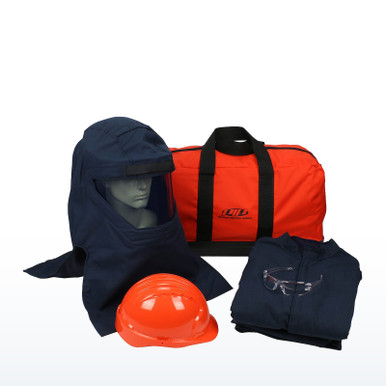 PIP 9150-540ULT 40 cal/cm² arc flash kitCoat, bib overall, hood with face shield, gloves and bag; rated 40 cal/cm² by the manufacturer
Why 1.2 cal/cm²? Incident energy is the heat that lands on a surface a set distance from an arc, measured in calories per square centimeter. Research on bare skin found that about 1.2 cal/cm² delivered in a fraction of a second is where a second-degree burn begins. NFPA 70E uses that figure as the line between "could be burned" and "would not be burned," so the boundary is simply the distance at which the heat from the worst credible arc has fallen to that level. Everything inside that line needs arc-rated protection; outside it, ordinary clothing is not expected to ignite or burn the wearer.
What does NFPA 70E say about the arc flash boundary?
The pieces of Article 130 that define, set and use the boundary.
What is an arc flash study (incident energy analysis)?
An arc flash study is the engineering work behind the label. An engineer builds a model of the electrical system: the utility supply, transformers, conductors, and every breaker, fuse and relay. From that the study calculates the available fault current at each piece of equipment, how long the upstream protective device takes to clear a fault, and then the incident energy a worker would receive at a normal working distance, usually 18 inches for low-voltage panels and motor control centers. The same calculation gives the distance at which the energy falls to 1.2 cal/cm², which is the arc flash boundary for that equipment.
NFPA 70E-2024, 130.5(G), incident energy analysis method; IEEE 1584-2018, Guide for Performing Arc-Flash Hazard Calculations, as the usual calculation method.The result is a table, one line per piece of equipment, and a label for each: voltage, boundary, incident energy and working distance. Clearing time is the number that moves the result the most. A breaker that trips in 2 cycles and one that takes 30 cycles can sit on the same bus and give very different boundaries, which is why changing a transformer, a breaker or a relay setting can make an existing label wrong.
NFPA 70E-2024, 130.5(G) informational note on system changes that affect the analysis (new in the 2024 edition); 130.5(H).When can the tables be used instead of a study?
NFPA 70E publishes a task table for ac equipment and one for dc equipment. Each row names an equipment type with a maximum fault current and a maximum clearing time, and gives the arc flash PPE category and an arc flash boundary for that row. If the actual equipment is within those parameters, the employer may use the table boundary without a calculation. If the fault current or clearing time is unknown or exceeds the row, the table may not be used and an incident energy analysis is required. The table and the analysis may not be mixed on the same piece of equipment.
NFPA 70E-2024, 130.5(E) (boundary from Table 130.7(C)(15)(a) or (b) where the tables apply), 130.5(G), 130.7(C)(15).How is the arc flash boundary different from the shock boundaries?
- The arc flash boundary is about heat. It depends on fault current and clearing time, not on voltage alone, so a 480-volt panel can have a larger boundary than a 4,160-volt switch.
- The limited approach boundary and the restricted approach boundary are about shock. They are fixed distances from exposed energized conductors set by voltage in Table 130.4(E)(a) for ac and Table 130.4(E)(b) for dc.
- The three boundaries are independent. Arc-rated PPE is selected from the arc flash boundary; rubber insulating gloves and insulated tools are selected from the shock boundaries. A worker often has to satisfy both at once.
- OSHA’s general industry rule says the same thing in fewer words: employees in areas with potential electrical hazards get electrical protective equipment appropriate to the body part and the work, and eye or face protection wherever there is danger from electric arcs or flashes.
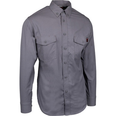
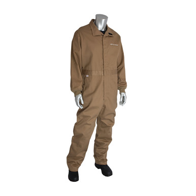
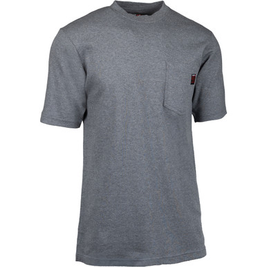
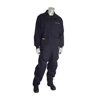
Arc-rated clothing and PPE by manufacturer rating
36 items · prices liveEach item shows the arc rating its manufacturer publishes (ATPV or EBT in cal/cm², or the PPE category the manufacturer states). Pick to the incident energy on the label, not to the boundary distance. Free shipping on orders over $199.
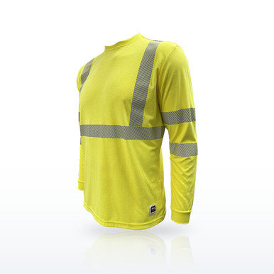
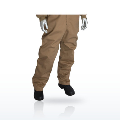
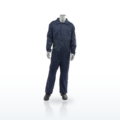

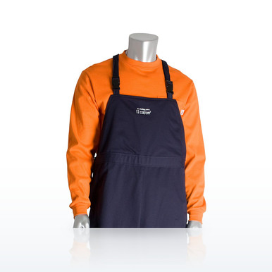
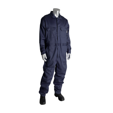
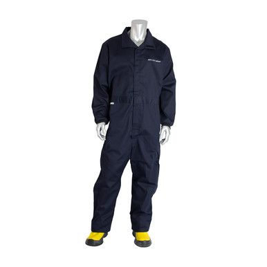
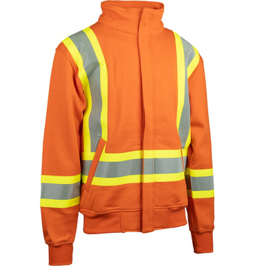
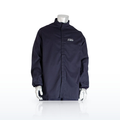
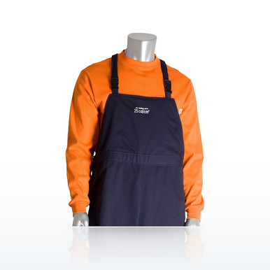
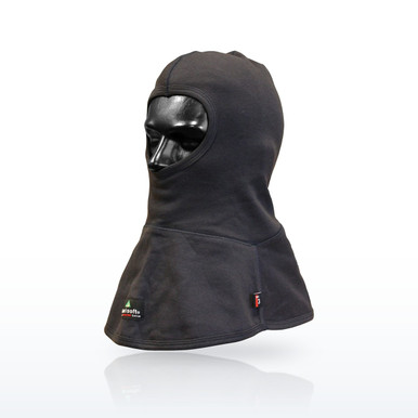
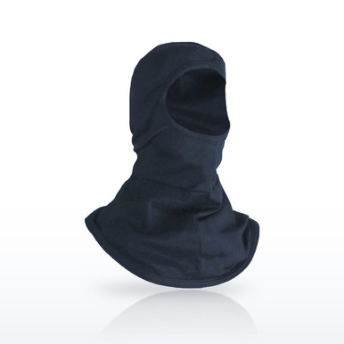
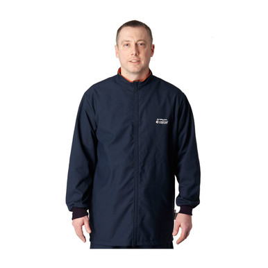
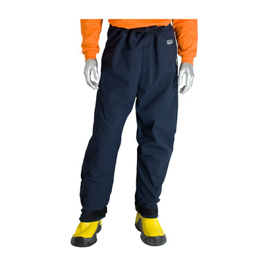
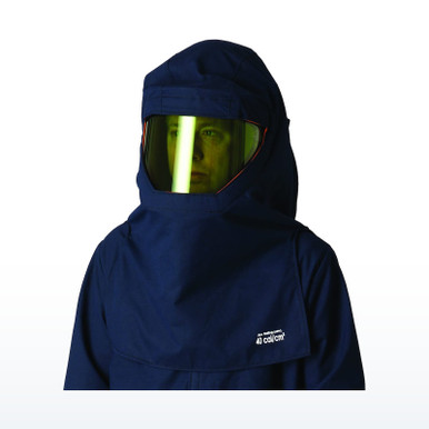
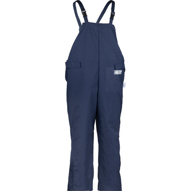
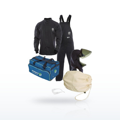
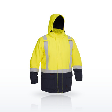
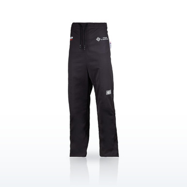
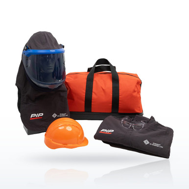
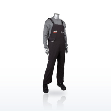
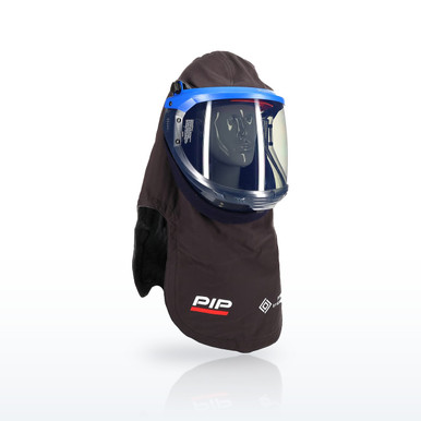
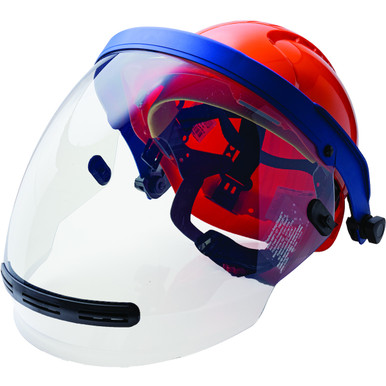
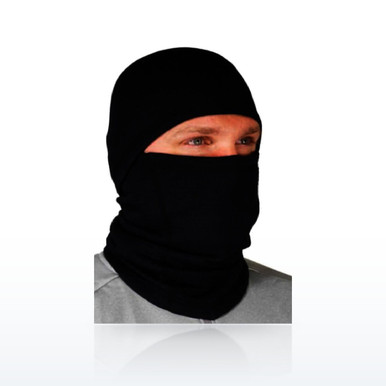
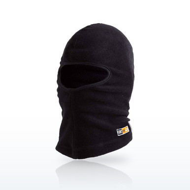
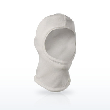
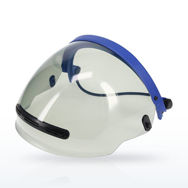
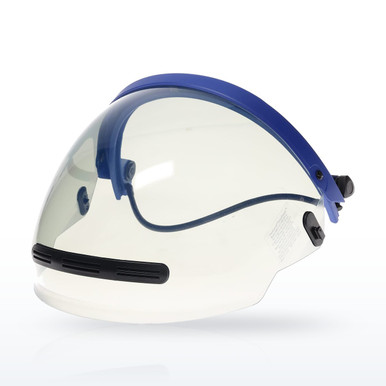
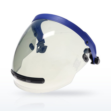
Rubber insulating gloves for the shock boundaries are in the work glove selector. Face shields and hoods are covered in their own guide.
Questions people ask
What is the arc flash boundary in simple terms?
The distance from live equipment at which an arc flash would still give an unprotected person a second-degree burn. NFPA 70E puts that at 1.2 cal/cm² of incident energy. Inside the line you wear arc-rated PPE; outside it you do not need it.
How is the arc flash boundary calculated?
From the available fault current, the clearing time of the protective device, the equipment type and the arc gap, using the IEEE 1584 equations in an incident energy analysis. For equipment within the limits of the NFPA 70E task tables, the boundary printed in the table may be used instead. (130.5(E) and 130.5(G).)
Is the arc flash boundary the same as the limited approach boundary?
No. The limited and restricted approach boundaries are shock distances set by voltage (Table 130.4(E)). The arc flash boundary is a burn distance set by incident energy. They are determined separately and either can be the larger one.
What is a typical arc flash boundary distance?
There is no typical number; it is calculated for each piece of equipment and can range from a few inches to well over 10 feet. The only reliable source is the label or the study for that equipment.
What is an arc flash study?
An engineering analysis of the electrical system that calculates fault current, clearing time, incident energy and the arc flash boundary for each piece of equipment, and produces the data for the labels. NFPA 70E calls it an incident energy analysis (130.5(G)).
How often does an arc flash study have to be redone?
NFPA 70E requires the arc flash risk assessment to be reviewed at intervals not exceeding 5 years and updated whenever a major modification or renovation takes place. A new transformer, breaker or relay setting can change the result before then.
Does OSHA require an arc flash boundary?
OSHA does not use the term in general industry, but 1910.335(a)(1) requires electrical protective equipment appropriate to the hazard and eye or face protection against electric arcs, and 1910.132(d) requires a hazard assessment. NFPA 70E is the consensus method employers use to meet those duties.
What has to be worn inside the arc flash boundary?
Arc-rated clothing and PPE with a rating at or above the incident energy at the working distance (or the PPE category on the label), hearing protection, a hard hat, and safety glasses or goggles. (130.7(C)(1), (C)(5), and Table 130.7(C)(15)(c) or Table 130.5(G).)
Standards and ratings on this page are as published in the documents named and by the manufacturers named. The employer’s hazard assessment and written program decide what applies at a given workplace. Verify a rating on the product and its spec sheet before use.